
About Inductors
Learn About Inductors
Basics About Inductor Design
In the use of the induction heating process, success depends to a great degree on the proper design of the inductions. Inductors for high-frequency induction heating usually referred to as heating coils, can be made in a large variety of types and styles- depending on the shape of the metal surface to be heated. Their designs must follow certain principles of maximum efficiency of the high-frequency generator to be obtained.
Generally speaking, localized induction heating is limited only by the ability to construct a coil to suit the surface to be treated and the capacity or power output of the generator. In other words, the generator should have sufficient power to heat the surface quickly. Then, if the shape of the part lends itself to a surrounding coil, the job is a logical one for induction heating.
Inductor Currents and Eddy Currents
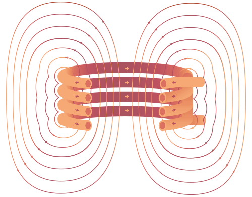
The eddy currents induced in the workpiece tend to be an image of the coil current. This is useful to bear in mind when designing coils for heating odd shapes. The magnetic field set up by a current is perpendicular to the current. The voltage induced by this field is maximum in a direction at right angles to the field, parallel to the original current. The result is that the eddy currents are parallel to the coil current within the limits imposed by the shape of the workpiece.
The eddy currents and the coil current also are attracted by each other. They are both concentrated near the surface because of the skin effect. When the frequency is low, there is less tendency for the currents to be attracted to each other than when the frequency is high. In general, if the frequency is high enough for efficient induction heating, the coil current and the eddy currents will try to be as close to each other as possible.
It is possible to heat almost any continuous shape on the surface of a flat workpiece. The currents induced in the workpiece follow the shape of the coil. The air gap between the coil and the workpiece plays an important part in this type of heating. The amount of flux that links with the workpiece diminishes rapidly as the space between the coil and the work is increased. The sharpness with which the heated pattern in the workpiece mirrors the shape of the coil is increased with frequency and with the closeness of the coil to the surface of the piece.
Coupling
Since magnetic fields occur in the area surrounding the coil and are stronger next to it than at any distance away from it, there is an advantage in placing the workpiece close to the coil so that the maximum amount of heat energy may be transferred to it. The strength of the field varies inversely with the square of the distance between the work and the coil, which means this consideration will have a direct relation to the amount of heat generated in a workpiece in a given length of time.
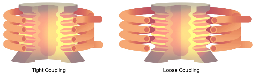
The term “coupling” is applied to the relative gap between the coil and the workpiece. A small gap gives “tight coupling” and a large gap gives “loose coupling.” Tight coupling is more efficient than a loose coupling because the reduction in the gap between the inductor and the work results in an increased concentration of the magnetic flux. The flux density at the surface of the work determines the rate of heating.
With multi-turn coils closely coupled to a workpiece, there is a tendency for the eddy-currents to provide a heat pattern corresponding to the helix of the coil. The wider the pitch, that is, the distance between the turns of the coil, the more pronounced this pattern will be – therefore, a closely wound coil and rotation of the work piece become essential. When the coil is loosely coupled, the stream of eddy currents spreads over a wider area and rotation of the work may not be necessary.
The lower the operating frequency the tighter the coupling required for a given result. The higher the frequency, the less critical the coupling requirements. This feature is of considerable importance when automatic feeding equipment is used.
Inductor Types
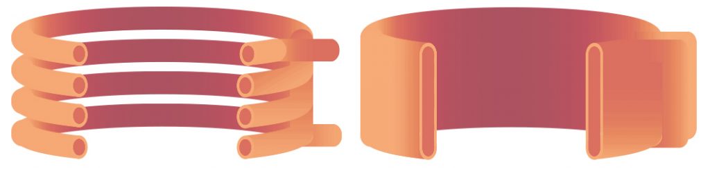
Induction coils may be either have a multi-turn design or be in the form of a single-turn coil, the latter often being termed a “solid” inductor. In either case, copper is variably used in their construction, and cooling by means of water is absolutely essential.
In making multi-turn coils of copper tubing, a wide variety of shapes is possible.
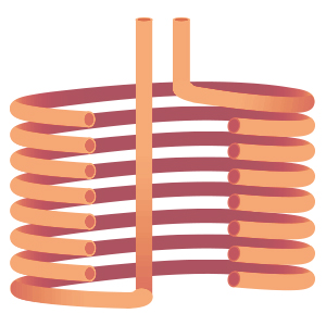
Solenoid Coil
The most common type of coil is a solenoid coil, suitable in surface heating of shafts and round parts.
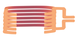
Square Coil
The square coil is suitable to heating outer surfaces of bars or shafts and can easily be formed and wound over a wooden block.
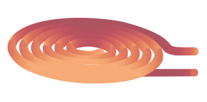
Pancake Coil
The pancake coil is used for heating flat surfaces.

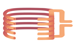
Channel Coil
The increasing need for higher production through mechanization or automation often makes it necessary to design coils through which the work can be conveyed, or only partially surround the work pieces and permit unimpeded passage on an external conveyor. Such coils are generally referred to as channel or conveyor type coils.
Formed Coil
Formed coils are designed for parts of intricate shape or necessary, specific heat patterns. As such, their appearance varies greatly, and are typically unique to the part.
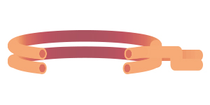
Internal Coil
Internal coils are used for heating inner surfaces of holes. Since the density of the magnetic flux is less on the outside of a coil than on the inside, and because the greatest strength lies next to the coil, there are several unique design considerations for internal coils. In order to be as effective as possible, it must be made in such a way that the overall distance from the surface of the hole being heated and the inner surface of the coil is held to an absolute minimum.